Archive
Blink using Arduino
Comments are very useful and I strongly encourage every sketch you make have acomment in the beginning with information like who wrote it, when you wrote itand what its supposed to do.
|
box-type
|
box-name
|
=
|
stuff-to-put-in-box
|
|---|---|---|---|
|
int
|
ledPin
|
=
|
13
|
The third part is an =, which basically says that the variable (box) namedledPin should start out equaling whatever is after the =
The fourth part is 13, a whole number (integer) which is assigned to ledPin
We also see in the middle there is a statement, we know its a statement becauseit ends with a ; (semicolon) however there’s a whole bunch more stuff before andafter it.
This bunch of code is an example of a procedure, a procedure is a collection of statements, itsused to group statements together so that we can refer to them all with onename. Its just like a procedure that we use to perform a task step by step.
|
returned value
|
procedure name
|
(input values)
|
{ statements }
|
|---|---|---|---|
|
void
|
setup
|
()
|
{ pinMode(ledPin, OUTPUT); }
|
To do this, the statement performs a procedure call. (We will use the phrasing calls aprocedure). Basically, we wantthe Arduino to take a break but don’t quite know how to do it, lucky for us,someone else wrote a procedure called delay which we can call upon to do the work for us. Kind of like if we needto do our taxes and we dont know how, we call upon an accountant to do it forus, giving them the paperwork input and getting tax return as the result.
|
procedure name
|
(input values)
|
;
|
|---|---|---|
|
delay
|
(1000)
|
;
|

Not a big deal, you can save it under a new name, such as MyBlink


Basics of arduino-Getting started
This lesson won’t teach any electronics, really. Its more for making sure that everything is setup and ready for the future lessons. It will verify the Arduino is working as intended and that the computer you are using is compatible.
Do you have everything you need?
For this lesson you will need some stuff! Make sure you have this stuff or you will be unable to complete this lesson
ImageDescriptionDistributor
 Assembled Arduino board, preferrably a Diecimila or Duemilanove (or whatever the latest version is) but NG is OK too
$35
 USB Cable. Standard A-B cable is required. Any length is OK.
Or any computer supply store
$5
9V DC power plug with 2.1mm barrel plug, positive tip
Optional
Any electronics supply store (Best Buy, Radio Shack, etc.)
$10
4 Rubber bumpers
Optional
These are included in Arduinos purchased from the Adafruit shop, otherwise any hardware store should have them.
$1
Preparing the Arduino!
Take your Arduino out of its protective bag. Look at it and make sure it looks kinda like this:

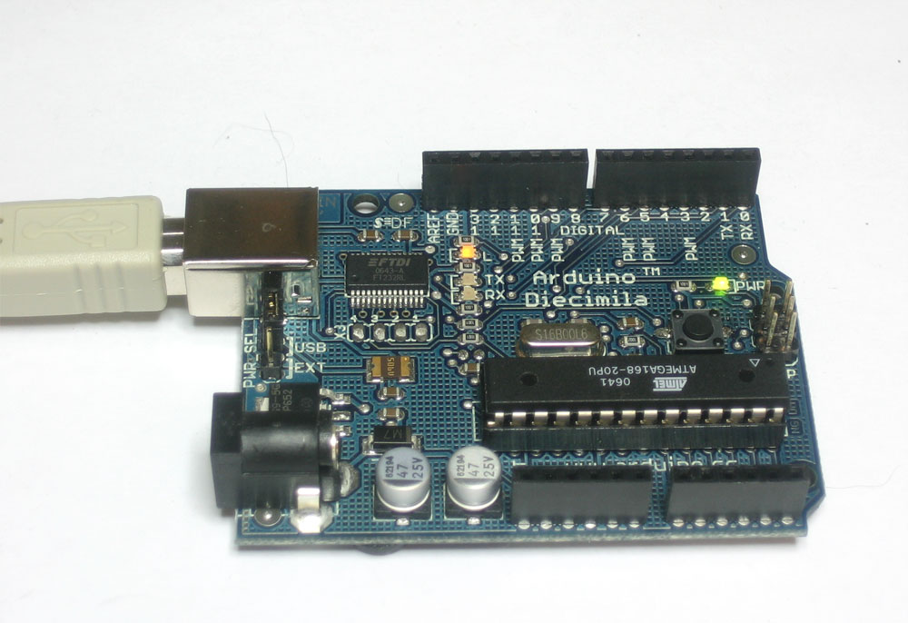
Diecimila Arduino
Or like this:
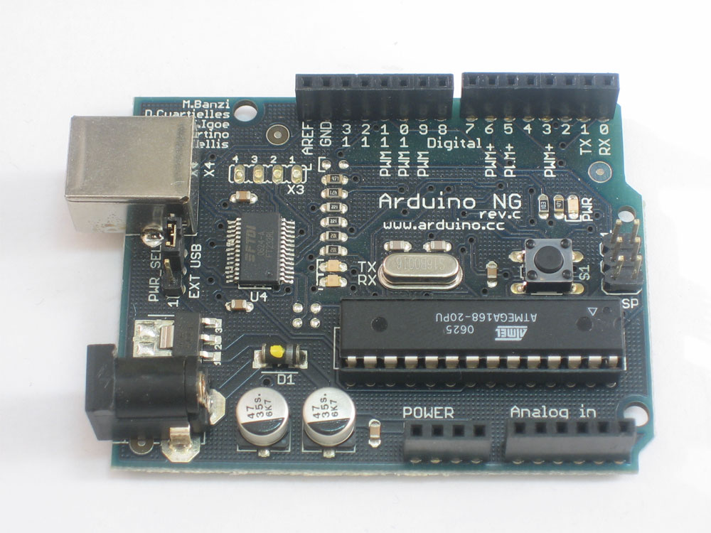
NG Arduino
If there’s anything missing or really wrong, make sure to contact the store you bought it from. For example, here is an Arduino that is missing the two round silver capacitors!

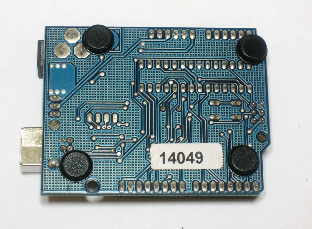
OK, now that you are satisfied that your Arduino looks good, put the rubber bumpers on the bottom of the board. This will protect your Arduino from spills and dirty tables. If your table is made out of metal, this is essential!
Download Driver
You’ll want to grab the USB drivers before plugging in the Arduino for the first time.
First, download the USB VCP driver from the FTDI website
I strongly suggest visiting the site and downloading the most recent drivers, as of Sept. 2007 the following links are the most recent.
Windows XP/2000/Vista
Mac OS X PPC
Mac OS X Intel, v 10.4 or higher
Linux v2.4 or lower kernel only!
If you have a Linux computer, and you have a 2.6 kernel, the driver is built-in and you are good to go. You can always run uname -a to get the kernel version.
Then extract the driver bundle onto the Desktop.
Under Windows use Unzip or rightclick and select “Extract All…”

Power up! (USB)
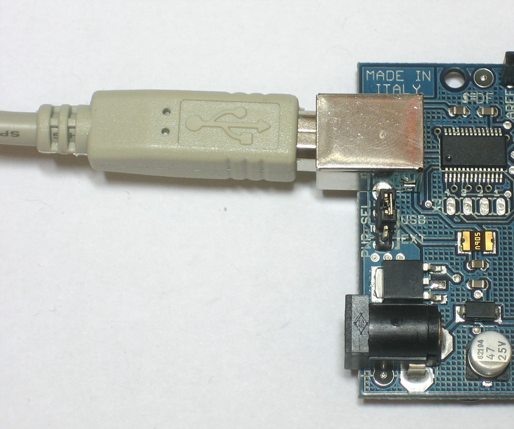
Now we are ready for the moment of truth, it’s time to plug your Arduino in and power it up. The most common way to do this is to plug one end of the USB cable into the Arduino and the other end into a computer. The computer will then power the Arduino.
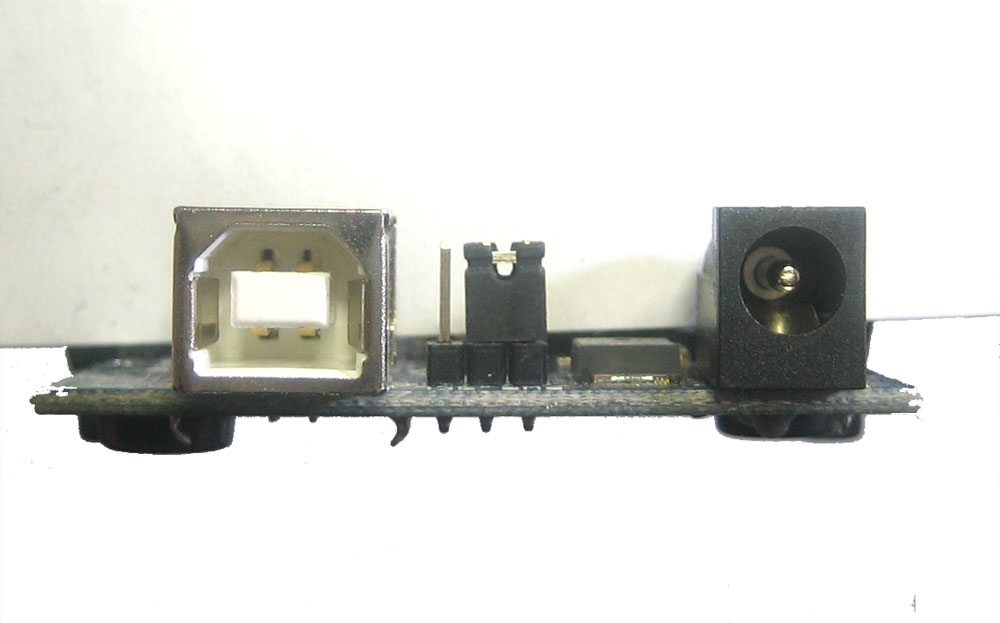
The jumper-setting step is only for Diecimila and OLDER arduinos! Make sure the Power Jumper is set correctly. Right next to the USB jack, there is a jumper with 3 pins. If the jumper is on the two pins nearest USB jack, that means you are planning to power the Arduino via the USB cable. If it’s on the two pins nearer the DC Jack then it means you are planning to power the Arduino using a 9V battery or wall adapter.
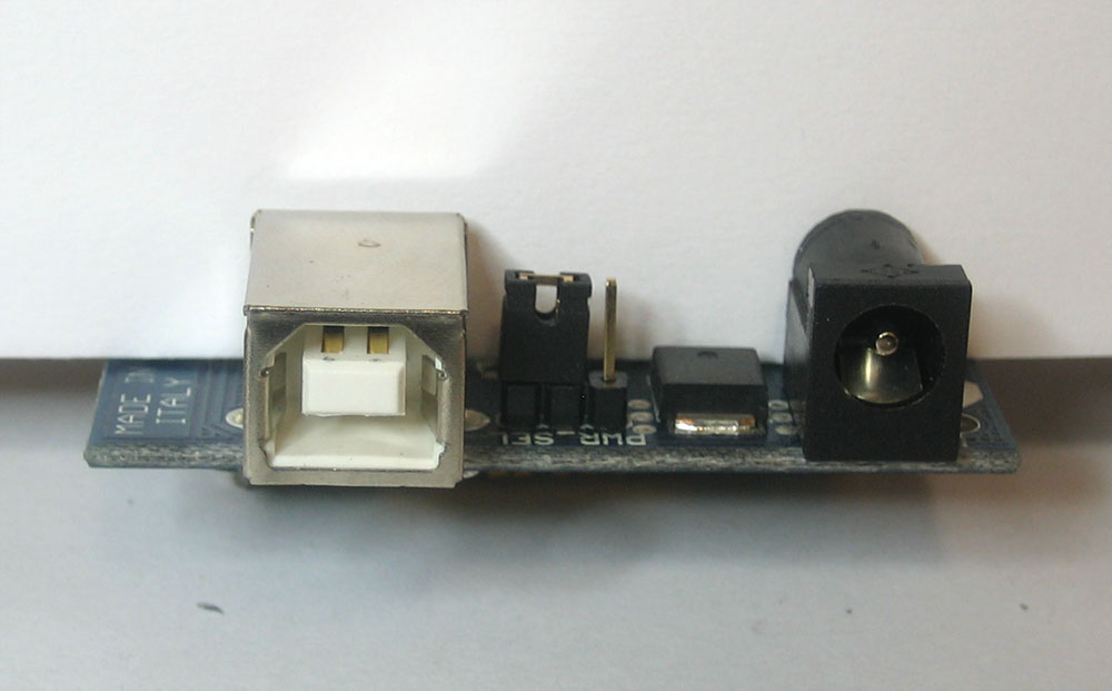
You’ll want it set as shown in the picture above.
Make sure your cable is a A-B cable. One end should be thin, rectangular. The other end should be square.
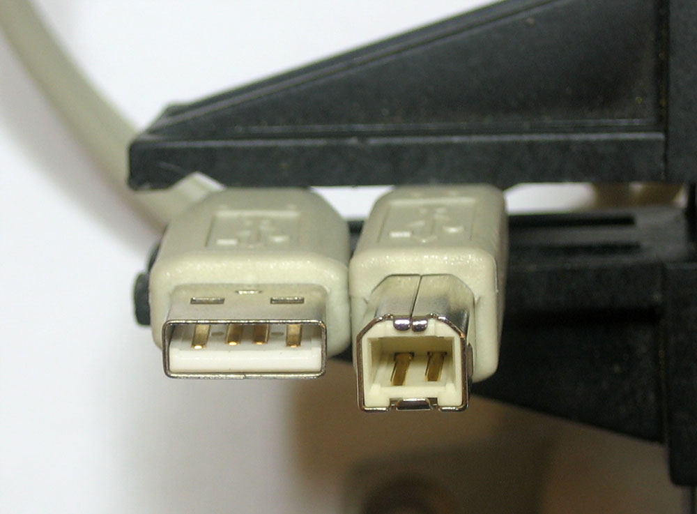
Plug the thin end into your computer

Make sure that the USB cable is plugged in directly to a computer port. Sometimes monitors or keyboards have a USB port you can plug into. Most of the time this is fine, but I strongly suggest you plug it directly into the computer as that will eliminate any possible problems. Same goes for USB hubs.
Later on, once you’ve verified you can power the Arduino and upload sketches no problem, then you can try plugging it into other ports.
Plug the square end into your Arduino
You should get a small green light on the right side of the Arduino, as shown here.
And a few blinking orange lights, on the left side, as shown in this video (download mp4 here)
If you’re plugging it into a Mac or Linux machine, you may not get as much blinking from the orange lights. The video is from plugging into a Windows computer.
If no lights or blinking occurs, double check:
Is the USB cable plugged into the computer and into the Arduino?
Is the computer on?
Is the jumper set correctly?
Try another USB port, USB cable, and computer
If you still can’t get it working, your Arduino may be faulty.
Next its time to install the driver! Follow these links for instructions for each of the supported operating systems
Windows
Mac
Linux
Power up! (9V DC, optional!)
Another way to power up the Arduino is to plug in a battery or wall adapter into the DC jack.
Verify that you have a 9V DC 100-500mA power adapter, with a 2.1mm barrel plug and positive tip. If the box doesn’t have any information about the adapter, you can look for these clues

Make sure the symbol near the bottom of the label is present. It means that the outside of the plug is negative and the inside is positive. A center-negative plug will not work with the Arduino.
To verify the DC plug is the right shape, just try plugging it in. If it doesn’t fit or is wobbly, it’s the wrong kind.
You can learn how to test wall adapters using a multimeter here.
The jumper-setting step is only for Diecimila and OLDER arduinos! Make sure the Power Jumper is set correctly. The jumper should be set so that it connects the two pins close to the DC jack
Plug in the adapter and verify you get the green light!
If not, double check:
Is the DC adapter plugged in?
Is the DC adapter the right kind? Check voltage, polarity, plug size, etc.
Is the jumper set correctly?
Try another adapter.
If you still can’t get it working, your Arduino may be faulty.
